Projects
TSoC (Tapas SoC)
[Tapas Services In-House Project]
[Oct 2023 - Present]
Currently this project is being developed on local git. The remote repo right now is a template of Efabless/Caravel_User_Project and will be updated after the first stable release.
Remote Git Repo: TSoC
RaaS-EDT (Robotics as a Service, ECU Diagnostics Tool)
[Tapas Services Proprietary In-House Project]
[Oct 2022 - Apr 2023]
Brief:
- Raas-EDT is an Automated Diagnostic Tool for Ethernet-based Automotive ECUs confirming the ISO 14229 standard. (Unified Diagnostics Services - UDS protocol)
- Based on the
Robotics as a Service - (RaaS)business model.
Usage:
- Any ECU that supports Ethernet and is ISO14229 UDS protocol compliant can use this tool.
- Simplified diagnostic command input for ECU vendors via plain text, with subsequent parsing and transmission to the ECU, while generating ASC logs and HTML reports from the responses.
- Basically, it is simple and easy to use with an excellent response time.
Design:
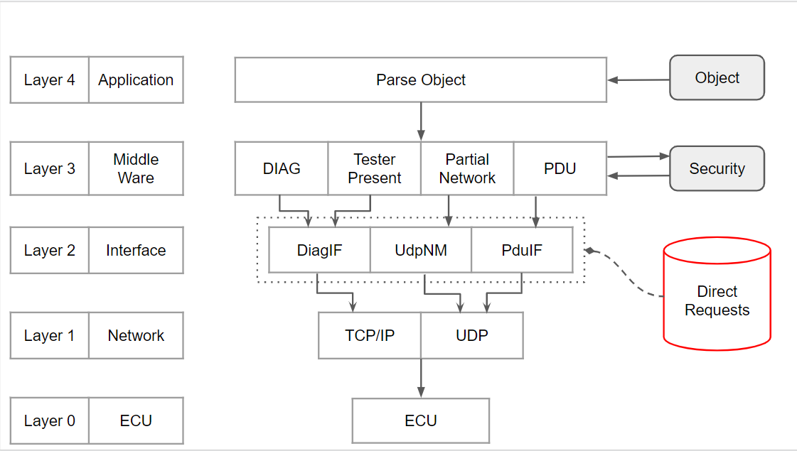
Explanation:
- Layer 0 ->
Physical Layer: Physical Connection of the tool with the ECU - Layer 1 ->
Network Layer: Tcp/Ip and Udp Connection - Layer 2 ->
Interface Layer: It acts as an interface between UDS (Unified Diagnostics Services) and the network layer. Users can directly use this layer to send raw requests to the ECU. - Layer 3 ->
MiddleWare. Various services likeDiagnostics (DIAG),Protocol Data Unit (PDU),Partial Network (PN)andTester Present (TP)are a part of this layer. MiddleWare receives the parsed requests from Application layer and further sends it to Interface. It receives response from Interface(if any) and validates it with the expected response. MiddleWare is also responsible for generating outputASCIIlogs andHTMLreports. - Layer 4 ->
Application Layer. User sends the request in plain text format and each request (treated as an object) is parsed to determine which type of UDS service is requested. After parsing it further sends the request depending on the type of service, to the MiddleWare. Security: MAC Authentication and security related module. This module is coupled with the MiddleWare.
Working:
- Requests can be sent either on command line or by writing to simple text file with an
.edtextension. - For sending request from command line use the argument
--cmdand runapp_main.pyalong with the arguments/requests (either Diag, TP or PN) in string format. - For running the
.edtfile, use the argument--edtand runapp_main.pyand pass theedtfile to be tested as argument.
External References:
- If you’re not familiar with what UDS protocol or ISO14229 does, please visit this wikipedia page: Unified Diagnostics Services
- In the Services section you can find various types of services that are supported.
Working:
- From Command Line:
- Refering the above Wikipedia link, if I want to send a
Diagnostic Session Controlrequest, to keep the ECU inDefault Session, I will just send this on command line: python3 app_main.py --cmd 'Default Session'
- Refering the above Wikipedia link, if I want to send a
- Using
.edtfile:- Create a text file with .edt extension. Let’s say I create a file to check whether the ECU is in Application mode or Boot mode and name it
AppOrBoot.edt. -
Now add commands to the file as shown in image.
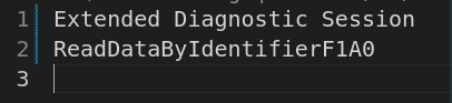
python3 app_main.py --edt AppOrBoot.edt
- Create a text file with .edt extension. Let’s say I create a file to check whether the ECU is in Application mode or Boot mode and name it
- These commands will be parsed by the
Application Layerinto a request, which is then sent to the ECU.
Services Supported by Raas-EDT:
- Services Supported -
Diagnostics(DIAG),Tester Present(TP),Partial Network(PN),PDU - DIAG: Just the
UDS_SERVICEname to be written. - TP:
TP(start, TesterID, TpPeriod) - PN:
PN(start, PN_1, PN_2, ...), PN_x are the Partial Networks that you need to send. - PDU:
PDU(PDU_Name): This is not generic as the ISO14229 and is ECU Specific
Report Generation:
- For every
DIAGrequest sent either via command line or in.edtfile, HTML report will be generated. - The HTML will contain the request and whether response received was positive or negative. If response is positive, HTML will log it as PASS else FAIL.
- If request is via command line the report will be generated in
Reportsdirectory asDiagnostics_Reportand current timestamp. If request is using the.edtfile, the report will be generated inReportsdirectory with same name as the.edtfile.
Logger:
- Logger is a seperate entity and is optional for use. To get the logs in
.ascformat, run theLogger.pyin a seperate terminal and simultaneouly send the diagnostics request. To end the logger just kill the process withCtrl+C. - Logs will be saved in
Logsfolder with current timestamp and in.ascformat.
Demo:
- We will create a
Testing.edtfile with the following diagnostic requests.Default Session DELAY(2) Extended Diagnostic Session DELAY(2) Default Session Extended Diagnostic Session TP(start, 0EF4EFFE, 2) DELAY(5) SecurityAccesslvl0x1 SecurityAccesslvl0x2 Default Session Extended Diagnostic Session SecurityAccesslvl0x3 SecurityAccesslvl0x4 Default Session Extended Diagnostic Session SecurityAccesslvl0x5 SecurityAccesslvl0x6 Default Session Extended Diagnostic Session SecurityAccesslvl0x7 SecurityAccesslvl0x8 Default Session Extended Diagnostic Session SecurityAccesslvl0x9 SecurityAccesslvl0xa Default Session Extended Diagnostic Session SecurityAccesslvl0xb SecurityAccesslvl0xc Default Session Extended Diagnostic Session SecurityAccesslvl0xd SecurityAccesslvl0xe Default Session Extended Diagnostic Session SecurityAccesslvl0x11 SecurityAccesslvl0x12 Default Session Extended Diagnostic Session SecurityAccesslvl0x13 SecurityAccesslvl0x14 Default Session Extended Diagnostic Session SecurityAccesslvl0x15 SecurityAccesslvl0x16 - Please refer the below video for a simple demo
- As it can be seen, firstly we start the logger from a different terminal before running the Raas-EDT.
- Next we run the
Testing.edtfile and as you can see how simply the commands written as above, get sent to the ECU and the ECU responds to those requests. - After that a HTML report is generated that shows which requests got positive response showing them as
Passand others asFail, while the ethernet log files get saved as.asclogs.
Extremum Seeking Control (ESC) for Maximum Power Point Tracking in Photo-Voltaic (PV) Cell
[Undergraduate Senior Year Project]
[Aug 2020 - May 2021]
Abstract: This project proposes designing an Extremum Seeking Control (ESC) for Maximum Power Point (MPP) Tracking in PV cell using L-Wang approach. The project focuses on the design and simulation of an efficient photo-voltaic system. PV cells exhibit nonlinear I-V characteristics and maximum power point that vary with solar irradiance. A voltage converter can therefore increase the efficiency by transmitting maximum power from the PV module to load by operating a solar cell array at MPP. In conventional control algorithms, even when MPP is achieved, the perturbation signal remains in the system which leads to steady state oscillations. A technique has been proposed to damp out the steady state oscillations. Also, the conventional approach has update law as proportional control. In this approach PID based update is designed which attains MPP faster and also contributes to reducing steady state oscillations. Simulation is used to evaluate the robustness of the proposed system. It is shown that the proposed system is robust to system uncertainties, environment changes and load variations. Advantages of this control algorithm are efficient tracking and zero oscillations about the steady state as compared to the singular perturbation Extremum Seeking Control model. Continuous measurement and control hence variations in the physical conditions are adjusted smoothly and rapidly. Disturbance observer scheme is used to estimate voltage of the PV cell. The DO scheme removes the need to use output voltage sensor. Sensor free design thus proposed contributes to less complications in hardware setup.